CAST
ZOID KITS
Hasbro Konig Wolf
Body, legs, armor pieces/details, skull, pilot controls
HCPC ventilator, overthruster housing, many details
Kotobukiya HMM Liger Zero Schneider
Shoulders, ankles, rear feet, hip structures,
Many hydraulics/details, HCPC/various armor,
Zoid Core “sled”, roll cage (sprue), joints,
Hip thruster pods, caps
Dark Spiner
Front feet, hind knee armor, rib vents
Core thruster baffles, shoulder armor,
Power exchanger intake housing
Gojulas Giga
Nose grating, shoulder detail,
Tail thruster base armor
Seismosaurus
Hind leg ankle armor, tail blade hydraulics
Killer Dome
Hind knee interior details
Dark Pegasus
Lower thigh armor, HCPC mount
Aerosaurer
Tail under-structure
Elephander
Tail blade mechanism
Dispelow
Skullcap armor
Shield Liger Commander
Articulated neck armor
Shield Liger
Chest mounted triple shock cannons
Guysack
Cockpit
NON-ZOID PARTS
Bionicle/Hero Factory
Shoulder/hip/torso/neck/tail joints, rear claws
HCPC housing/armature/barrel/sight/
Recoil absorption unit, tail structure
Sheet Styrene
Front folding claws, hind saw blades,
CAS armor parts, tail blade, overthruster baffles
various cosmetic and support structures
Lancet Blood Sugar Meter
HCPC barrel
Mega Bloks Struxx
HCPC barrel/sight, cap supports,
Core exchanger cable anchors
Iwata HP-B nozzle
HCPC barrel
Tube Styrene
HCPC recoil absorption unit,
Foreleg hydraulics
Tube Aluminum
HCPC recoil absorption unit,
Foreleg hydraulics, shoulder pod struts
Micro Screws
Forward claw pins, various details/reinforcements
Semiconductors
Hind knee detail bolts, EMP catalyzer
Torso detail components
120 Volt AC Jack
EMP cannon barrel
Warhammer 40k Rhino Tank
Tail structure/armor
Kodak Coolpix Camera
EMP emitter, neck armor detail,
Inner mouth details
Coil Springs
Shoulder pod struts
Heroclix Autobot
Shoulder armor base structure
Struxx
HCPC rest, cap support posts
Necklace Chains
Core exchanger primary cables,
Detail cables for HCPC, tail & torso
Rayon Cord
Torso detail cables
Fender Guitar “G” String
Tail support/cable details
Magnets
CAS attachment
Rayon Cord
Power cables
NODS & GLIMPSES
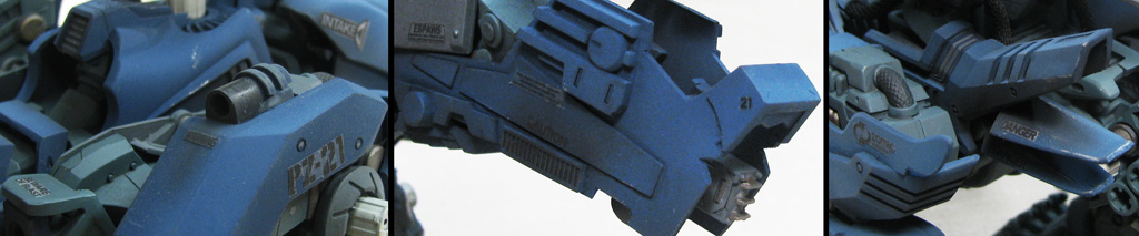
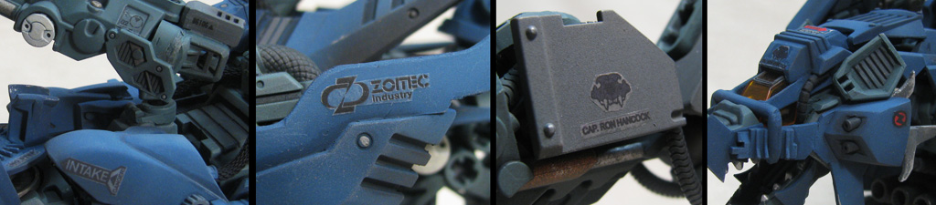
I also wanted to make certain I used some iconic Zoid decals to tie it to the line and for nostalgic reasons: “ESPAWS”, “BEWARE OF BLAST”, and even a few instructional OJR stickers made their way onto the Wolvereaver’s armored hide. Incidentally, I chose the serial number PZ-21 for “Prototype Zoid: #21”, a salute to the OJR kits with the “21st Squadron” labels on them. This is also the only kit I have made (custom or stock) that uses the Zoitec corporate logo stickers.
AN INWARD GLANCE
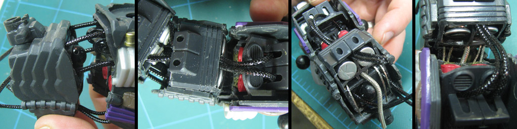
With the completion of the Wolvereaver’s body and armor, I returned to detailing the build… from the inside out. Ever since my Siobahn custom, I have worked to create internal details of my builds. That means filing open voids with interesting components and filling out the silhouette so that there are no obvious, “toy-like” gaps around my joints, especially the torso. One of the best ways I have found to do this is by running cables through the torso segments; they create a lot of visual interest while adding the appearance of legitimate function.
The first three images above show the hallows I used to run cables through the Wolvereaver’s body. The yellow marks outline voids existing in the original molds for the Konig Wolf; the band of narrow ones in the middle were where the wiring and main drive shaft were located. This band was between the motor/drive assembly in the large, upper void and the bisected battery compartment in the lower void. The upper void was filled with the actual joints, so I used my trusty computer components to fill the lower voids. Initially, I intended to leave the band empty because it looked structurally cool on its own. The red marks outline the holes I had to drill through the walls capping these compartments in order to run a series of 6 cables of some kind. To keep them flexible and visually rugged, I've continued using the Rayon-wrapped chords I had began using on Eradicator.
CABLES: A BELLY FULL
The final cable layout took more than an hour to thread; with the black Rayon cables being super light, thick, and stiff, and the metal ones being so heavy, thin, and dangly, they all fought for dominance as I tweezed them one by one into their sockets. Just as with Eradicator, all of the cables have to be pulled out before the custom is painted, then re-inserted.
STAGE 1 ENDS; STAGE 2 BEGINS
It is always a remarkable difference when a custom reaches priming stage; with no changes other than the unifying color, a custom transitions from a kitbash into a kit. It is always at this stage when you can rest from wondering if all of those bits and pieces are going to pull together… they certainly did.
FINAL IMPROVEMENTS
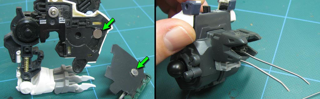
During the cleaning and pre-painting phase of the build I decided to make some late improvements. The first photo is showing the locations where I installed two pairs of power magnets. While the shoulder CAS fit very well, it was tricky to keep on, especially while posing; the magnets snap the armor securely into place and make posing a breeze. The second photo deals with a problem I encountered as I finished the tail. With a core structure of Bionicles and a full CAS in place, the tail had become very heavy. It was taxing the base joint, and I wanted more dynamic tail poses to be possible. I threaded a length of g-string (an actual “g” string for a guitar, folks, not a bikini bottom!) through the hip segment. The ends of the wire pass through a gap in the first tail segment and act as both a support spring and aesthetically as a pair of power cables.
WOLVEREAVER: PRIMED
Priming this build required a bit more finesse than other customs I’ve constructed. Rather than using a can of spray primer, I decided to preserve as much detail as possible by airbrushing the entire model with thinned down Gunship Gray military paint. It looks almost identical to primer gray (I have used it to touch up primed models in the past) and the airbrush application allowed me to keep whole limbs intact as well as obtain a perfect, very matte coat with minimal buildup.
CABLES: THE FIRST RUN
Running short on stout serpentine necklace chains, I decided to try using the same Rayon wrapped cord that I used with great success on Eradicator. My real concern with these cords was that, on a smaller model, they were not as flexible, they were a little bulky, and they tend not to hang as pleasingly like metal chains. For the short spans between torso segments in the Wolvereaver, they proved to do a good job, however. The first two images above show the Rayon cords passing through the center segment effectively, but there was still something missing. I decided to grab some of my smaller square chains and the last segment of one of my larger ones and run the five through the flat, wide series of openings between the chest cavities. The final two shots above show the metal chains laced through amid the Rayon ones; 11 cables altogether.


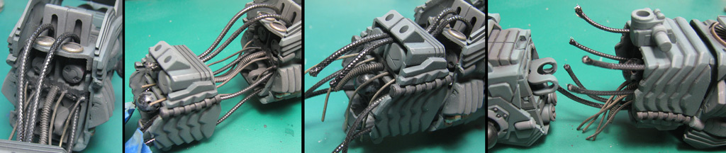
FINAL THREADDING
Now I have learned my lesson! I know to securely glue them all into one segment, then threading them through; in this case, I secured them inside the chest and worked my way through the hips and into the waist; the cables are NOT secured at the hip, allowing them to push and pull a bit so the torso can be flexed with minimal binding. Note that there are two subtle differences in the final cables; the metal strands across the middle have been replaced. The original round central cable was swapped for an oval one, and the four flat outer cables replaced with round ones. The reason for this last minute change was twofold: 1) the new cables had greater flexibility and 2) they were not stainless, so they could be painted to appear darker in concert with the Zoid’s final color scheme.


BIG GRAY BEASTY
In order to see if any parts required adjustments, the whole Wolvereaver had to be constructed after the priming stage and before the final paint stage. Since much of this custom will be the medium military gray, this step is a very good indicator of the final model’s appearance. With the primer in place the entire build feels more solid and a touch heavier… and it certainly lends a great deal of weight to the appearance as well.

WOLVEREAVER’S TRUE COLORS
After quite a lot of indecision on the subject of color schemes, I finally decided that the original was the best. This scheme was actually created by David Silva based on the original American “Robostrux blue team” scheme; specifically the models Terrox and Brutox (Gojulas and Redhorn). The cold, rugged terrain theme of the Zoid spoke well though the cool blues and desaturated teal and gray.

BASE COLORS
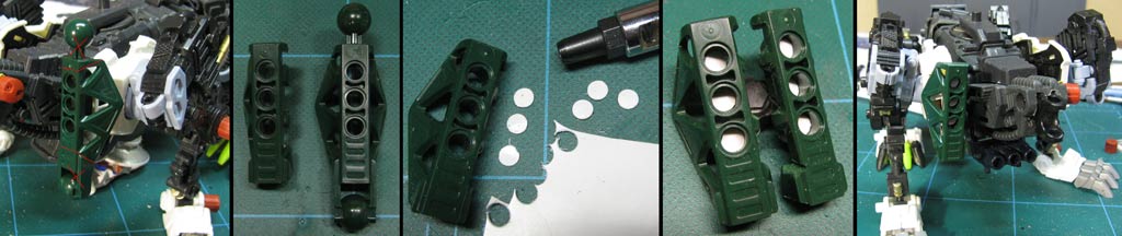
When choosing the colors for the structure and armor, I wanted to stay very close to the original Robostrux theme but still wanted to accent the details found in both the HMM Liger Zero parts and the Konig Wolf kit parts. These kits have some remarkably similar structures that already tie them together, but the right colors could really blur the lines where they transitioned. I have seen many artists paint individual panels, bolts, and structures with strikingly different colors to make them “pop”, but I really wanted Wolvereaver to feel a bit more realistic (if that’s the word to describe a 100+ ton sentient wolverine-tank). I custom blended a subtle steel/brown to give some parts a little sheen, but the base structure would remain largely the desaturated teal with gunship gray (you can see the pieces to the left of the “5-hole plate” are in gray in the first image). To unify the parts, all circular pieces around the caps are gray, and all rivets on the custom are the custom metallic gray/brown. The armor retains only the shade lines and the occasional rivet, but has been left otherwise plain.
DECAL DIFFICULTIES
One of the toughest visual elements to decide upon for the Wolvereaver was the application of decals. For a more “traditional” looking kit white works very well on the base colors, popping out boldly… but a bit too boldly. Black decals, on the other hand, were harder to see but felt more “legitimate” for the direction of the build, more of a “low visibility” effect. Decals with finer text would all but disappear against the dark blue, and there was little room for them on the HMM parts due to all the sculpted details. The images above don’t quite capture the contrast seen on the kit in person; the blacks are a bit darker in real life, and the edges of the labels are barely apparent (it’s amazing what the camera can see that we can’t). Notice on the third picture that this Zoid is piloted by my father, who is a captain in a fire department but is a US Navy vet. The wolverine skull is a custom decal I created in Illustrator based on a real photo. In the final pic you can see the only color on the kit’s labels; the 2056 era “Z” Helic logo and the “Rescue” label for the emergency ejection handle atop the head.
FINAL ASSEMBLY
And so my two year long journey comes to an end (well, an average of 1-2 hours every couple of days with a 6 month hiatus where my garage was all but inaccessible)... at least 200 hours of work. On the whole, I am pretty satisfied with my interpretation of the original Wolvereaver drawings, especially given the parts I had on hand. The form is by no means exact, but I’m glad I was given some license to build the custom. Still, considering the original was intended as a bat-op kit and I redesigned it as a fully articulated kit, I think it turned out quite well. There are still a number of things that make me twitch, however, and that will definitely shape my policies when building customs for commission!
FINAL ASSEMBLY – (continued)
As my first ever full CAS custom, I must say that the hardest single part of this build was in making an entire Zoid from someone else’s specs… and then building a suit of armor for it! Beneath that armor my Wolvereaver is still very true to the original, though with a nitpick here and there. My only real regret in the structure is the nasty kink in the tail… while it looks quite good in armor, I do wish I would have bulked up around the joint just a little to smooth the transition between the pieces. Again, overall, I do feel good about this model… but I would like to feel great about it.

FINAL BUILD: CONCLUSION
At the end of the day, can I say I am satisfied that my work was done to the best of my ability? Considering how much of this custom was a learning curve, I will actually say, yes. If I built it again (and, perhaps I just might, someday, so I don’t have to sell it!) I think I could do it better. The most important reaction is that from my client, who seemed to be ecstatic over the build. THAT, then, is the measure I shall use to determine if the PZ-21 Wolvereaver was a success… and a success it is.

FINAL THOUGHTS
I have learned a lot of techniques on this custom, and I’m certain I could do things better, faster, and stronger (any Daft Punk fans out there?) on my next build. I’m looking forward to new challenges, and to building customs on commission, though I know I’ll be sad to see each one go. Building the Wolvereaver signifies the end of an era for me, and the beginning of another. I think I’ve started off on the right foot.
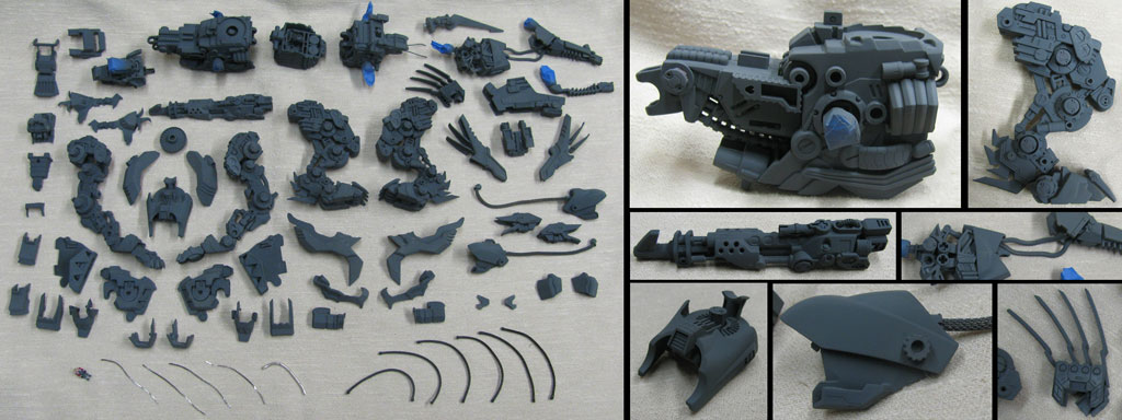
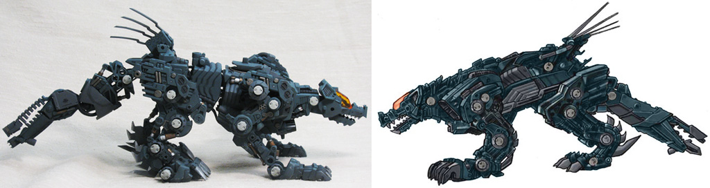
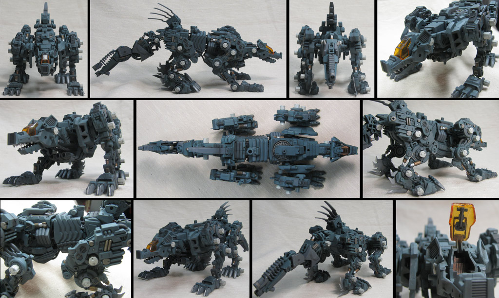
GALLERY: STRUCTURE
As this Zoid is leaving my hangar for good, I thought I would collect a fair number of pictures before it sets off on missions beyond my borders. I will never get another opportunity to see it again (extremely likely), so I took myriads of redundant photos before it heads for parts unknown. This gallery is just to show off its natural state, sans armor. As with Eradicator, there are many details which vanish beneath the CAS.
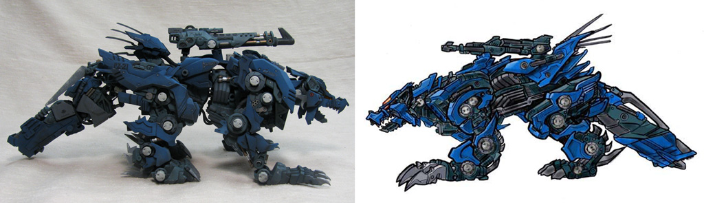
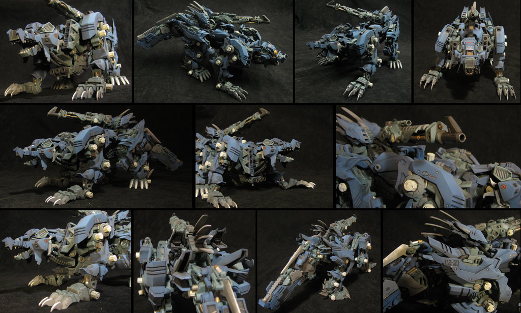
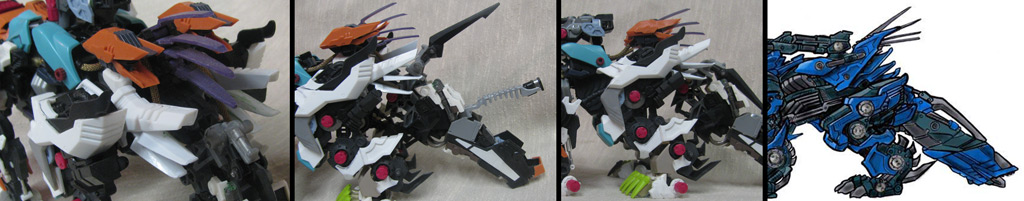
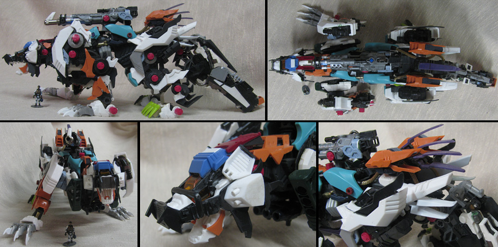
GALLERY: FULL ARMOR
The Wolvereaver as it was always intended to be seen; a rugged, tough machine ready to open up a can-o-hurt on its enemies! My camera casts a bit of a yellow hue against the darker background, but it does capture some of the look and feel of the Dullcoted skin. I really like how it turned out, especially features like the small bits of metal peeking out from between the plates. It was definitely worth the time and effort, and looks true to the sketches.
GALLERY: DIORAMA BASE
Hey, I’ve got a decent base for shooting customs, may as well use it on the baddest custom I’ve made to date. While hanging out in town isn’t the Wolvereaver’s natural environment, it seems to look at home here, too… if just to protect its den.
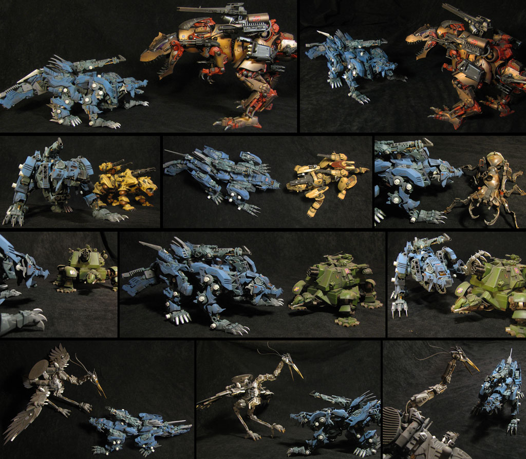
GALLERY: COMPARISONS
Finally, it can often be helpful to see a custom in the presence of other Zoids to offer a sense of size, detail, and style. I’m also filming it with some of my own customs, as it will likely never share its place among them on my shelf… yet it will always be among the best of them.
TRIVIA
Time to Create
240+ Hours
Sources for parts
33
Articulations
54 Joints
CAS
40 Pieces (+1 Core)
Original Stats vs. Build Stats:
Length: 30.2 meters Length: 3 meters
Width: 12 metersWidth: 1 meters
Height: 13.0 metersHeight: 1 meters
“Firsts” on This Build
First commissioned Zoid
First build of a design not of my own
First inclusion of a Zoid Core
First use of HMM components in a custom
First full CAS build (Eradicator was close, though!)

PZ-21 WOLVEREAVER
Part II
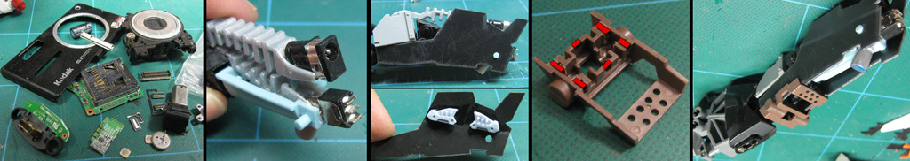
CAS: SHOULDER WEAPON PODS
On the illustrations, each outer torso/shoulder is capped with a 3-shot missile box. I stumbled upon a pair of Bionicle pieces that were effective for creating the front of the box, though the armor was a bit different than the illustration. It did, however, work well with the look of the structures beneath. After being carved up to fit the front of the shoulders I decided they would need to be capped inside; the nature of the CAS and of the existing shoulders made designing them with full-depth tubes and removable missile impractical at best. I punched six disks out of styrene card and glued them inside the tubes. I could now display the missile box as empty or affix warheads inside the holes to give the illusion of depth.
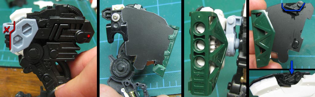
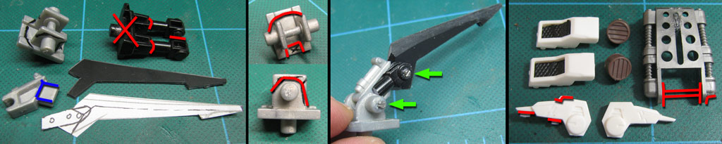
CAS: SHOULDER WEAPON PODS - (continued)
Carving up the triple-port pods was all well and good, but finding the way to lock them onto the body without interfering with the redundant jointing of the torso/shoulder/leg. On the first image I trimmed the front of the leg both to better match the image and to make room for the CAS plating. The trick with image #2 is that you are seeing the inside of the shoulder, held up by the leg. The strangely cut black styrene covers the wild shape of the shoulder pieces to give a more secure fit. Image #3 shows a close-up of the missile pod with a detail I added inside the grille; a piston with real spring shock. Finally, the last image shows the weapon’s locking mechanism; the top cleat locks into the top of the shoulder piece and the lower nub locks into a hidden port for stability.

CAS: SHOULDER WEAPON PODS - (continued)
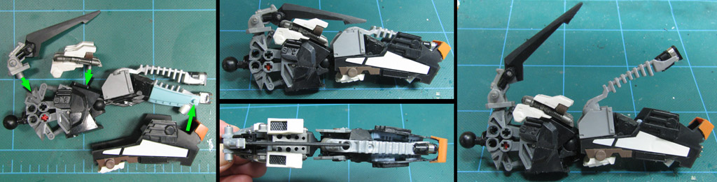
It’s fortunate that half of the legs are based on the HMM Liger Zero because there are several sockets useful for affixing armor, as shown on photos #1 and #2. The second pic also shows where the modified Konig armor is fitted to the HMM structure. There are several places where details like the micro-screw on photo #3 is used to make the Zoid look more solid and functional. Also in this shot, the white LZ piece fills another boring gap and makes the leg look just a little more substantial while offering support to the CAS. Photo #4 demonstrates all of the armor pieces created for the forelegs while #5 shows all of the armor in place.
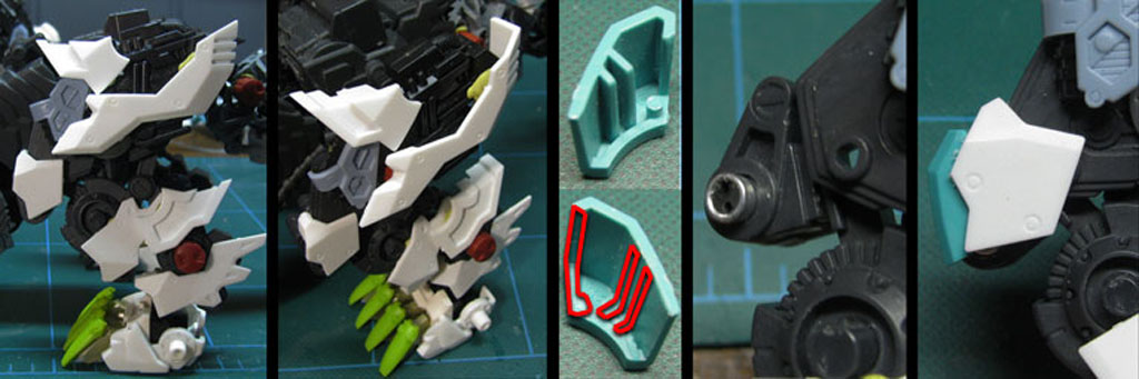
CAS: HIND LEGS
The first two frames here show the results of playing around for more than an hour just to find the right bits to create anchor points for the CAS than I can use to build the armor upon. I wanted to keep as close to your drawings as I could in form, knowing that I would probably be doing a lot of filling and shaping in the end. The third frame is the surgery I performed to make a Dark Spiner kneecap fit a Wolvereaver. I love this next detail; that is the new knee of the 'Reaver; it is the ankle of the Konig Wolf reloacated; the hole is plugged with a transistor that passes perfectly through and just pokes out the other side (it will give a nice raw metal look on the finished model). What you can't see in this shot is the ankle "tendon" hydraulic is still present behind that angular armor. The last frame shows the new removable knee armor in place.

CAS: MORE HIND LEGS
Working down the leg, the first shot shows some of the trimmings and gluings of KW armor to fit the new design. I added HMM hydraulics for details, so I had to dremmel some seats for them in the armor; in the end these really help keep the armor in place. The two blue arrow shots show the result of my new cement. I inquired at the hobby store what was the best cement to give a super strong welt to different kinds of plastics (I didn't want this thing to fall apart on your shelf, and Testor's cement becomes brittle with time) and they suggested Pro-Weld. The stuff is so strong that I decided to "finish" several pieces of armor to make them more complete; I've never had glue good enough to make hanging pieces and support members like these! Frame 4a/4b... okay, I dug through parts for nearly two hours trying to come up with a solution to the new ankle armor to get it close to your drawings! This was so hard because I wanted to retain the look but had added an HMM ankle joint. I chose to use these seismosaurus bits with a lot of modification. The lower pic shows my new heavy black styrene I am now using for some builds. In this case I capped the open inner leg and added Wolvereaver's "saw spikes" at the same time. The last frame I just wanted to show you a couple of details; the top arrow points to the lower hip armor box seen on your drawings... it's the wing-shoulder from an Evil Pegasus (now a $400 model, incidentally!) The lower arrow shows a thruster port I made from a snippet I had to remove to make the new ankle work. I held onto that piece for months knowing I would find it a home!
HIND LEG: FINAL STRUCTURES
The completion of the hind leg structures was one of those project milestones that helped to inspire me onward. The first frame above shows how much detail has been placed on the inside of the leg. There will be another few features added, such as flexible cables at the heel and possibly to the mini thruster at the rear knee cowling, but essentially the leg is completed at this stage. A Killer Dome gear was used to fill in the gap of the knee but a really cool cosmetic piston and real spring was removed in favor of retaining actual joint flexibility. The second frame shows the leg with the 5 pieces of armor in an exploded view. Frame 3 shows the leg with all of the armor in place to compare it with the actual drawing. My leg is not quite as long as David Silva’s, but I may be able to make some more changes to bring it closer yet.
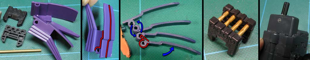
THE TALE OF THE TAIL
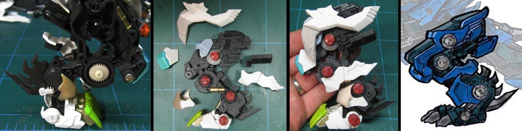
To build the tail I spent a great deal of time poring over the drawings I was given and rooting through my parts bins. What did not sit well with me was that this custom was as articulated as an HMM kit, but the tail was to have only one joint at the base. The drawing had some form of claw located in the tail and what appeared to be a blade as well; this thing should be agile for infighting. This decision created a lot of problems as I now redesigned for not one but four joints.
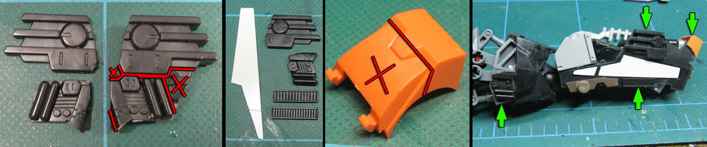
The first image above shows the basic structure I decided upon; Bionicles are your best friend. They matched the basic shape and were strong pieces. There was actually a LOT of cutting and sanding to shape the internal pieces and black outer shell bits. I used an Aerosaurer tail part to fill in the lower half of the end segment and gauged the shape and features from there. The last two pics show my removing a Bionicle plug to fill in an unsightly gap under the armor; I also planned to use this piece to thread some cables between the completed assemblies.
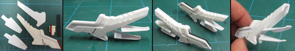
DETAILS; INSIDE & OUT
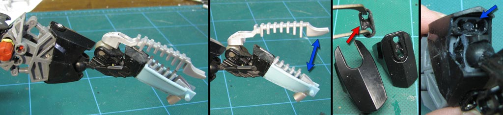
Here we finish the tail as well and begin its armor. First you detonate an old Kodak digital camera, and then you install those components into the tail tip to create the EMP cannon. The internal structure is then encased in a scratch-built armor shell. The two inside structures on pic #3 help clip the armor to the rails on either side of the lower tail section. The fourth shot is of a lower weapon housing from the HMM Liger Zero's shock cannons. With a little surgery it clips the armor panels together.
CAS: FOREWARD TAIL
I interpreted a structure atop the tail as some kind of blade rather than a handle-like adornment. This became yet another pain in the posterior as the blade would attach on the other side of the joint I had contrived. To make it work, I had to redesign an Elephander joint to fit the new tail. I cut the blade out of two pieces of black styrene and attached a pair of hydraulics cut from a Seismosaurus piece to add strength. To complete the articulating blade, I drove four microscrews into the bits for detail. The final image above is for a "saddle" that adds armor to the sides and top of the front half of the tail. It also adds a pair of exhaust/maneuvering thrusters. This unit had to nest on the outsides of the tail structure and beneath and around the blade.
CAS: REAR TAIL
This series transitions from the tail structure to the CAS. The first pic shows how I salvaged the LZ's discarded shoulder bits and managed to carve another pair of detail panels from them. The upper portion will be used on the armor, the lower section to add some detail to the tail structure. Shot #2 shows CAS details mounted on each side of the shell including scratch built panels to break up the monotony of the surface and two different brands of zip ties to act as a vent both outside and inside each half. That orange bit of Schneider armor had to be cropped to create the bridge at the top of the tail tip; it was required to make the armor hold on tight and yet still be able to pop off. The final pic shows the placement of all of these parts in the tail (which is rapidly growing in complexity).
CAS: TAIL ARMOR IN PLACE
The final tail assembly! Main structure + aft armor + forward armor/thruster pack + blade! It looks rather beefy, like the drawing, but it can still articulate at the base and the mid-point. The last image is the finished tail with the blade and EMP cannon elevated on the E-Mag Grappling Claw.
CORE VENT/THRUSTER BAFFLES
A prominent feature of the original design was a kind of ducted fan-bladed… thingy. It seemed like some sort of a vent and had large pipes fed into it from the Zoid’s torso around the main gun. I decided it was such an obvious feature that it shouldn’t be simply static. I took two foot pads from the HMM Liger Zero kit with their perfectly made sockets and the tops of a Dark Spiner’s thigh armor to create the baffles themselves. After a lot of cutting and shaping, I cut four brass tubes to create function hinges for the thruster box. Then I sunk a post into the original power switch position and sunk a screw into it for strength.

CAS: HIP THRUSTERS
Things got tricky in the hip region. There are a pair of thrusters that feature on the CAS, but the hips have also undergone a serious structural change with the addition of articulation. I made another command decision to build the thrusters as articulated units as well, building two thrusters from the HMM kit as they were originally designed; though a slight departure from the illustration, their scale and form was still quite close to the drawings. I modified the power switch cover to accept the thruster posts. If the owner wished, he could take off the trusters and keep the core vent system to emulate the original illustration.

COMBINED THRUST SYSTEM
Finally assembled, the dorsal and hip thruster system creates a display of variable pitch baffles that imitate the fur of a ticked off wolverine… which I’m pretty sure was the entire idea. The hip thrusters are also mounted to rotate on their posts, adding a direction element to their function.
CAS: OVERTHRUSTERS
This feature of the build is probably the part where I took the most liberty; sure, there were places I added details and joints, but they were usually based on the drawings and work-arounds for adding articulation. The very last thing I had to work out was the array of fins beneath the high-back mounted core-vent system. On the drawings this area appeared as a form of multi-layered, articulated back armor, but try as I did, I could not find a solution that worked well with the existing model’s structure, especially after making the hip thrusters articulating pods.
I finally decided to try and make the armor layers into baffles for yet another pair of thruster units. These were made using the trimmed down tail armor of the Konig Wolf with a backing of card styrene. To add to the structural integrity and some detail from the front or back, I trimmed down a small piece of HMM Liger Zero armor. The front of the unit then had a grill added by using a zip-tie. The baffles are, unfortunately, static, though they appear to articulate. Each is made of shaped styrene card. I created a mounting peg out of white sprue, then reinforced it with a micro-screw.
CAS: OVERTHRUSTERS IN PLACE
The overthruster pods mount to the hip through a hole left after the original pegs were removed. They snug down between the pelvis and the thigh, and also tuck in just behind the center torso power exchanger pods. The shape of the baffles are designed to help tuck in and direct the power hoses as they pass around the core vent pod and proceed to the tail. Though the look is a bit of a departure, the designer loved them, as they really brought out the angry wolverine hackled look.
PRE-PAINT ASSEMBLY
Here is the first (and last) time I put all the pieces together before priming. It's actually quite impressive to see the smatterings of color, each representing a different kit. It is also a good time to take note of features such as the use and locations of sheet styrene versus actual model parts. While the cabling had been planned at this stage, it had yet to be permanently installed.